
Electric Actuator Controllers & Drivers
Controllers and drivers needed for our electric actuator family. You will find step motor, servo motor and card motor controllers as well as 24VDC Fieldbus gateway units and AC servo drivers.
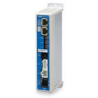

24VDC Controllers, Single Axis
Single-axis 24VDC controllers provide high-performance motor control for both step and servo motor types. While step motor controllers are optimized for high workloads at low speeds, the servo motor variants provide consistent maximum speeds across their full range, making this series a versatile solution for precise automation and transport tasks.
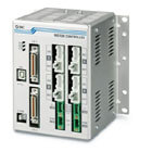
24VDC Controllers, Multi Axis
The JXC series of multi-axis controllers is designed to save space and reduce wiring by controlling three or four 24VDC step motor actuators within a single compact package. These controllers enable complex coordinated movements, such as 2-axis circular interpolation and 3-axis linear interpolation. They support up to 2048 lines of step data and feature speed matching capabilities to ensure stability and orientation during multi-axis transport.
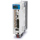
AC Servo Motor Drivers
LE’s AC servo motors drivers are engineered for high-speed, high-acceleration applications that require greater torque than DC variants. Many models include advanced features such as real-time tuning, vibration suppression, and Safe Torque Off (STO) functionality to ensure precise and safe motion control in demanding automation environments.
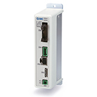
LATCA, Card Motor Controller for LAT3 Series
The LATC4 controller exclusively operates the LAT3 magnetic drive card motor. Laptop software is easy to follow, including screens for step data and I/O setup, as well as monitoring and testing operations. The easier of two step data entry modes requires only target position, positioning time, and load weight.


Manifold Controller
The JXD1-M manifold controller system provides a highly efficient, modular solution for controlling up to 16 axes of LE2 electric actuators through a single gateway unit. By utilizing a manifold configuration that consists of a fieldbus gateway, multiple 1- or 2-axis actuator drivers, and a termination unit, this system significantly reduces the physical footprint and wiring complexity compared to traditional standalone controllers.
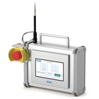
Electric Actuator Teaching Pendant
Electric Actuator Teaching Pendants offer a convenient alternative to using a laptop for configuring and testing electric actuators. These portable devices connect directly to the controller to allow users to set step data, monitor status, and perform jog tests or alarm resets in the field. They simplify the setup and troubleshooting process for both single-axis controllers and integrated-motor actuators.
Controller Driver FAQs
Q: Can multiple controllers be linked together on a network?
A: Yes. The LEC-G series gateway unit converts Fieldbus network protocols and allows you to connect up to 12 individual controllers to a single PLC network. Our controllers and drivers support various communication interfaces to ensure compatibility and ease of integration.
Q: What is the difference between the LECP1 and LECP2 programless controllers?
A: Both are designed to be used without a PC or a teaching box, but they behave differently:
- LECP1: You can manually teach and set up to 14 discrete stop positions using the forward, reverse, and set buttons located on the actuator driver panel.
- LECP2: This controller is designed to mimic a traditional pneumatic air cylinder. It features a stroke study function that automatically registers both stroke end positions with a 3-second button press.
Q: How does the LECPA pulse input type controller work?
A: Instead of moving to pre-programmed step points, the LECPA actuator driver is controlled by pulse signals from the customer's PLC positioning unit. This allows for continuous motion and high-precision positioning at any point.
Q: How many stop positions can be registered per controller?
A: The maximum number depends on the controller type:
- JXC51/61 & LECA6: Up to 64 points
- LECP1: Up to 14 points
- LECP2: Up to 14 points (2 stroke end points + 12 intermediate points)
- LECPA: No step limits, as the position is dictated by incoming pulse signals
Q: Do I need a computer to configure these controllers?
A: No, a PC is not necessary. Depending on the model, you have three options:
Directly on the controller: (LECP1/LECP2 only) Using the physical position-selecting switches and buttons.
Teaching box: A handheld controller with a screen that can store multiple step data points and transfer them to the driver.
PC software: Using a computer via a USB connection.
Q: What is the difference between easy mode and normal mode?
A: Easy mode: Users only need to input the desired position and speed, and all other conditions are automatically pre-set.
Normal mode: Designed for complex configurations, it allows users to set detailed parameters, measure waveform data, review alarm details, and set up customizable plug-in functions.
Q: Can these controllers perform pushing or gripping applications?
A: Yes, they include a force limit function. The controller can switch between standard positioning operations and pushing operations. In pushing mode, the motor applies continuous force without triggering a motor overload alarm.
Q: When are incremental encoders required?
A: If you are using the older or more basic models like the LECP1, LECP2, LECA6, or LECPA, you must use an incremental encoder. If you are using the JXC51/JXC61 series, you can use either an incremental or a battery-less absolute.
Q: Are there any situations where I would need an external resistor?
A: Yes. External resistors are required if you are wiring an NPN/PNP open collector output from an external sensor to a device that expects a different voltage, or if you are tapping into a raw LED indicator circuit. However, for direct communication between the SMC controller's I/O cable and a 24 VDC PLC, external resistors are unnecessary.
Q: What power supply is necessary?
A: SMC controllers and drivers require a 24 VDC power supply, typically with an allowable voltage fluctuation range of ±10%.
Q: What happens when an alarm is generated?
A: The controller immediately stops the actuator. Depending on the severity of the alarm, it will either perform a controlled deceleration to a stop or cut motor power.